

Wind load resistance calculations for terracotta systems involve determining the maximum wind pressure that ceramic facade elements can withstand without structural failure. The process requires evaluating building height, location, facade orientation, and mounting system specifications to ensure compliance with local building codes and structural safety requirements.
What is wind load resistance and why does it matter for terracotta facades?
Wind load resistance refers to the ability of building facades to withstand horizontal and vertical forces generated by wind pressure and suction. For terracotta facades, this calculation determines how much wind force the ceramic elements and their mounting systems can safely handle without detachment, cracking, or structural failure.
Wind forces create both positive pressure on windward surfaces and negative pressure (suction) on leeward surfaces. Terracotta facades must resist these alternating forces while maintaining structural integrity. The ceramic tiles themselves are typically strong enough to handle wind loads, but the mounting system connections become the critical failure points that require careful analysis.
Proper wind load calculations prevent facade failures that could result in falling tiles, water infiltration, or complete system collapse. Building codes require these calculations to ensure public safety and structural performance throughout the building’s lifespan. Insurance and liability considerations also make accurate wind resistance calculations essential for project approval.
How do you determine the basic wind pressure for your building location?
Basic wind pressure determination begins with identifying your building’s wind zone classification using regional wind maps provided by national building authorities. These maps categorize geographic areas based on historical wind data, topography, and exposure conditions to establish baseline wind speeds for structural calculations.
Most building codes provide wind speed maps that show basic wind speeds for different regions, typically measured in metres per second or kilometres per hour. These speeds represent the fastest mile of wind expected to occur once every 50 years at a standard height of 10 metres above ground in open terrain.
The basic wind pressure formula converts wind speed into pressure using the equation: q = 0.613 × V², where q is the dynamic pressure in Pascals and V is the basic wind speed in metres per second. This calculation provides the foundation for all subsequent wind load determinations on your terracotta facade system.
What factors affect wind load calculations for ceramic facade systems?
Building height significantly influences wind exposure, as wind speeds increase with elevation above ground level. Taller buildings experience higher wind pressures, requiring more robust mounting systems and potentially smaller ceramic tile formats to manage the increased loads effectively.
Facade orientation determines whether surfaces experience positive pressure (windward) or negative pressure (leeward). Corner locations and building edges create particularly challenging conditions with increased suction forces that can exceed standard wind load assumptions for terracotta installations.
Surface roughness of the surrounding terrain affects wind flow patterns. Urban environments with numerous buildings create turbulence that can either reduce or amplify wind forces. Open rural locations typically experience more consistent but potentially higher wind pressures on terracotta facades.
Building shape coefficients account for how architectural features like corners, parapets, and rooflines modify wind flow. These geometric factors can create pressure amplification zones where standard wind loads may be insufficient for ceramic facade design requirements.
How do you calculate the actual wind load on terracotta elements?
Actual wind load calculation multiplies the basic wind pressure by several modification factors, including height coefficients, shape factors, and dynamic response considerations. The formula typically follows: Wind Load = Basic Pressure × Height Factor × Shape Coefficient × Safety Factor.
Dynamic pressure calculations consider how wind gusts interact with the building structure and facade system. Terracotta facades with lightweight ceramic elements may respond differently to wind forces compared to heavier masonry systems, requiring specific dynamic analysis for accurate load determination.
Safety factors typically range from 1.5 to 2.5, depending on local building codes and the consequences of failure. These factors account for uncertainties in wind prediction, material properties, and installation quality. Higher safety factors may be required for tall buildings or critical facade areas.
The final wind load calculation must consider both ultimate strength requirements (preventing failure) and serviceability limits (preventing excessive deflection). Terracotta mounting systems must satisfy both criteria while accommodating thermal movement and building drift.
What safety standards and building codes govern terracotta wind resistance?
International building codes such as the International Building Code (IBC), Eurocode 1, and national standards like AS/NZS 1170 provide the framework for wind load calculations on terracotta facades. These codes specify minimum wind speeds, calculation methods, and safety factors required for structural approval.
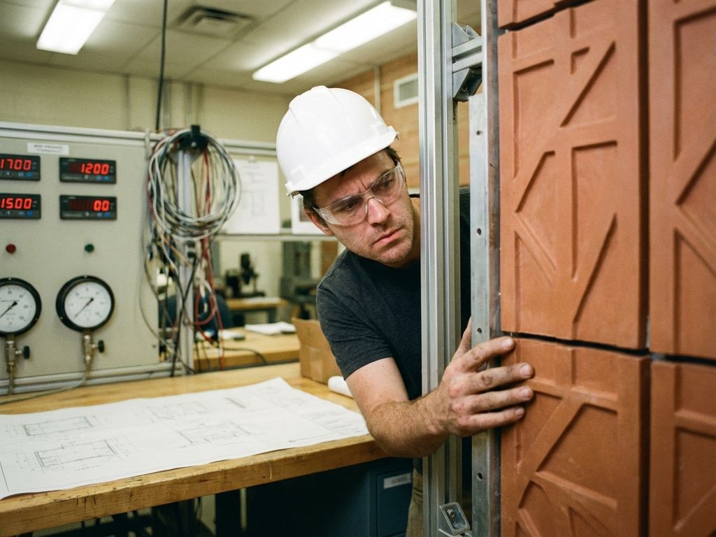
Testing standards such as ASTM E330 and EN 13116 establish procedures for evaluating facade system performance under simulated wind loads. These tests verify that terracotta mounting systems can withstand calculated pressures without failure or excessive deflection under controlled laboratory conditions.
Local building authorities often supplement international codes with regional requirements based on specific climate conditions or seismic considerations. Coastal areas may require additional corrosion protection for mounting hardware, while earthquake zones need integrated seismic and wind load analysis.
Compliance documentation typically includes structural calculations, test reports, and installation specifications. Professional engineers must seal these documents, taking responsibility for the adequacy of wind resistance calculations and system performance predictions.
How does TONALITY® help with wind load resistance calculations?
TONALITY® ceramic facade systems address wind load requirements through comprehensively tested mounting solutions and detailed technical documentation. The lightweight ceramic elements reduce overall wind loads while maintaining structural performance through engineered back-profiling and interlocking connections.
Key technical support includes:
- Structural testing data for various wind load conditions and mounting configurations
- Pre-calculated load tables for standard building heights and exposure conditions
- Technical drawings showing proper installation details for wind resistance
- Engineering support for complex facade geometries and high-wind applications
- Compliance documentation packages for building approval submissions
The aluminium retention profiles and ceramic element interface have been specifically designed to transfer wind loads safely to the building structure. Contact TONALITY® technical support to receive project-specific wind load calculations and mounting system recommendations for your terracotta facade application.
Related Articles
- How do architects create parametric and computational terracotta facade designs?
- What building types benefit from terracotta cladding?
- 7 Cultural Institutions with Iconic Terracotta Facades
- How do BAS terracotta installation methods work?
- What terracotta colors and glazes work best for different building contexts?