

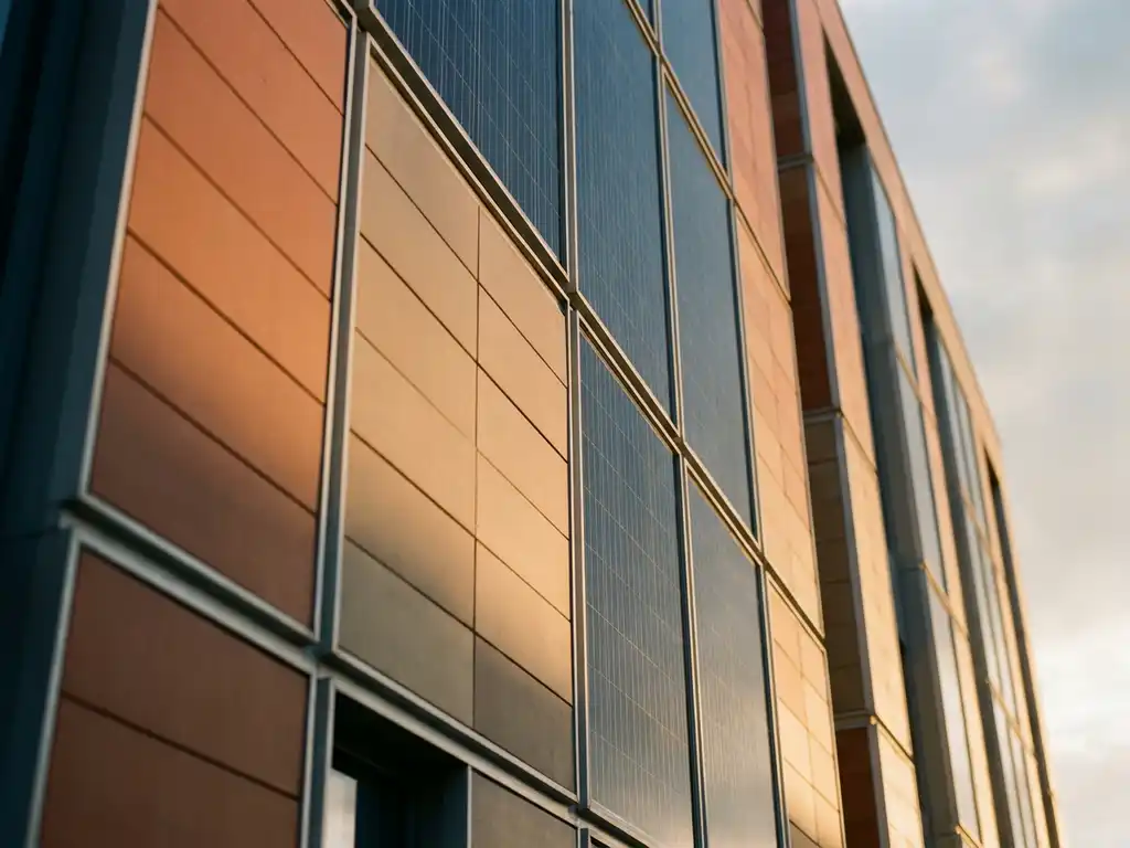
Yes, ceramic cladding solutions can be integrated with building-integrated photovoltaics (BIPV) within the same facade system. The two technologies are compatible when carefully coordinated at the design stage, particularly within ventilated rainscreen assemblies where each layer of the facade performs a distinct function. The sections below address the most important technical and design questions architects face when combining these systems.
How does BIPV technology work within a ventilated facade system?
BIPV panels replace or supplement conventional cladding elements by generating electricity directly from the building envelope. Within a ventilated facade, solar modules are mounted onto the same substructure as the cladding material, with the air cavity behind them serving a dual purpose: it allows heat generated by the panels to dissipate, which improves electrical efficiency, while also providing the pressure-equalised drainage function that protects the building fabric from moisture.
The ventilated cavity is particularly important for photovoltaic performance. Elevated panel temperatures reduce energy output, so the natural convection of air rising through the gap keeps modules cooler than flush-mounted alternatives. This makes ventilated facade systems one of the more technically sound environments for BIPV deployment compared to compact or direct-fix cladding assemblies.
Electrical cabling runs within the cavity or through dedicated conduit channels in the substructure, connecting to an inverter system typically located in the building’s service core. This integration requires early coordination between the facade engineer, electrical engineer, and architect to ensure cable routing, access points, and inverter locations are resolved before detailing begins.
Which facade zones are best suited for BIPV panel placement?
South-facing elevations at angles between 15 and 60 degrees from vertical receive the most consistent solar radiation in the northern hemisphere, making them the primary candidates for BIPV panel placement. East and west facades can contribute meaningfully to morning and afternoon generation, respectively, while north-facing elevations are generally not viable for photovoltaic output in temperate climates.
Beyond orientation, shading analysis is critical. Zones that fall under overhangs, adjacent structures, or are interrupted by window reveals, balconies, or service penetrations should be avoided or carefully modelled before BIPV panels are specified. Even partial shading can significantly reduce the output of an entire panel string if the modules are wired in series.
Spandrel panels between window bands and solid wall sections above parapet level are often the most practical locations. These areas typically offer uninterrupted surface area, are structurally straightforward to detail, and sit at heights where access for maintenance can be planned systematically. Architects working with completed facade projects often find that the most successful BIPV integrations treat energy-generating zones as deliberately composed elements of the overall facade composition rather than additions applied after the design is resolved.
Can ceramic facade panels and solar modules share the same substructure?
Ceramic facade panels and BIPV modules can share the same aluminium substructure, but only when the system is engineered to accommodate the different load profiles, fixing requirements, and thermal movement characteristics of both materials. The substructure must be designed with sufficient rigidity and load capacity to handle the combined dead weight, wind loads, and any additional framing required by the solar modules.
Ceramic cladding elements typically use vertical aluminium retaining profiles with rear-profiled interlocking connections, while BIPV modules generally require a framed or frameless mounting rail system. These two fixing methods can be coordinated on a shared primary grid, but the secondary fixing details will differ between zones. Expansion joints and movement allowances must account for the differing thermal coefficients of glass-based solar modules and ceramic tiles.
One practical advantage is that ceramic panels have a low surface weight, which reduces the overall load on the substructure and creates more headroom for the additional weight that solar framing and cabling introduce. This is particularly relevant in timber construction, where substructure capacity is more constrained than in steel or concrete-framed buildings.
What design limitations does BIPV integration impose on ceramic facades?
BIPV integration introduces several constraints on facade design freedom. Solar modules are manufactured in standardised rectangular formats, which creates a module grid that must be reconciled with the ceramic tile layout, window positions, and overall facade composition. Mixing two distinct panel geometries on the same elevation requires careful modulation to avoid visual conflict.
Colour and reflectivity are also affected. Standard photovoltaic cells have a characteristic blue or dark grey appearance, though black monocrystalline cells and coloured or printed glass options are available at a premium. These options offer greater design coherence when paired with ceramic cladding in darker tones, but they typically involve trade-offs in energy output compared to standard cells.
Maintenance access is another constraint. BIPV panels require periodic inspection and, in the event of failure, individual module replacement. This means the facade layout must incorporate accessible zones or provision for temporary access equipment, which can influence the placement and extent of ceramic cladding in adjacent areas. Architects should also account for the visual impact of wiring, connectors, and junction boxes, which need to be concealed or integrated into the substructure detailing. Reviewing the available surface and format options early in the design process helps identify ceramic elements that complement rather than compete with the solar module grid.
How does fire performance compare between ceramic cladding and BIPV modules?
Ceramic cladding is classified as building material class A1, meaning it is non-combustible and contains no combustible components. BIPV modules, by contrast, incorporate polymer encapsulants, backsheets, and framing materials that are typically classified in the B or C fire rating categories, depending on the specific product and certification. This difference has direct implications for facade specification on buildings where A1 non-combustibility is required across the entire envelope.
In mixed facades where ceramic and BIPV zones are combined, the overall fire classification of the facade system is determined by the least fire-resistant component. Architects specifying BIPV on buildings subject to strict fire regulations, such as high-rise residential or certain public buildings, must verify that the solar modules carry appropriate fire test certification for the intended application and that the system as a whole meets the relevant national building regulations.
The ventilated cavity common to both systems requires fire barriers at floor levels and at the boundaries between combustible and non-combustible zones. These cavity barriers must be detailed to maintain the integrity of the ventilation function while preventing fire spread through the air gap. Early engagement with a fire engineer is strongly recommended when combining ceramic and BIPV elements on regulated building types.
What should architects specify when combining ceramic cladding with BIPV?
When specifying a combined ceramic and BIPV facade, architects should address the following areas explicitly in the project documentation:
- Substructure coordination: Define the primary grid dimensions to accommodate both ceramic fixing profiles and BIPV mounting rails, with clear responsibilities for each trade.
- Fire classification requirements: Specify the required fire rating for each facade zone and confirm that BIPV modules carry the necessary certification for the building type and height.
- Thermal movement allowances: Document the expected movement for both ceramic and glass-based solar elements and ensure expansion joints are detailed accordingly.
- Cable routing and access: Specify conduit routes, junction box locations, and maintenance access provisions within the facade assembly drawings.
- Aesthetic coordination: Define the module grid, ceramic tile format, and joint alignment strategy to ensure a coherent visual outcome across energy-generating and non-generating zones.
- Maintenance protocols: Include facade access requirements in the building manual, distinguishing between ceramic cladding inspection and BIPV module servicing intervals.
Procurement sequencing also matters. BIPV modules often have longer lead times than ceramic tiles, and the substructure design cannot be finalised until both products are confirmed. Early engagement with suppliers on both sides prevents coordination gaps that are costly to resolve on site. Technical documentation and samples can help resolve format and fixing compatibility questions at the design development stage rather than during construction.
How TONALITY® supports ceramic and BIPV facade integration
TONALITY® ceramic facade elements are engineered to work within ventilated rainscreen systems of exactly the kind that BIPV integration requires. For architects coordinating mixed-technology facades, TONALITY® offers several specific advantages:
- A1 non-combustibility: Every TONALITY® ceramic element is classified as building material class A1, providing a clear fire-safe baseline for the non-BIPV zones of the facade.
- Low surface weight: At approximately 40 kilograms per square meter, TONALITY® panels place minimal load on the substructure, leaving greater structural capacity for BIPV framing and mounting hardware.
- Precision manufacturing: Tiles produced to within one millimetre tolerance, in formats ranging from 150 x 300 mm to 400 x 1,600 mm, allow the ceramic module grid to be coordinated precisely with the solar panel layout.
- Wide design range: A broad selection of colours, surfaces, and formats means ceramic zones can be specified to complement the visual character of the BIPV panels rather than compete with them.
- Simple substructure compatibility: The rear-profiled interlocking system mounts onto vertical aluminium retaining profiles that can be coordinated with standard BIPV mounting rail systems on a shared primary grid.
If you are working on a project that combines ceramic cladding with solar integration, the TONALITY® team can advise on format selection, substructure coordination, and technical documentation. Get in touch with the sales team to discuss your project requirements directly.
Related Articles
- How do ceramic cladding solutions support biophilic design strategies in architecture?
- Terracotta vs HPL (High-Pressure Laminate): Which Performs Better Long-Term?
- Terracotta vs Brick Slips: Choosing the Right Clay-Based Cladding
- Where should movement joints be placed in terracotta cladding?
- Are terracotta facade systems worth the investment?